Arduino Robot 3 - Part 1 - Reflectance Sensor
This is the first part of my post covering my creation of the line following Arduino robot. In this post I will talk about the costs; setup and preparation for creating the robot. I will also discuss a few different approaches to line following that I explored. We will get the sensor attached to the robot and retrieving data. In the next part, we will cover the final approach used; tour the code, and see the full video.
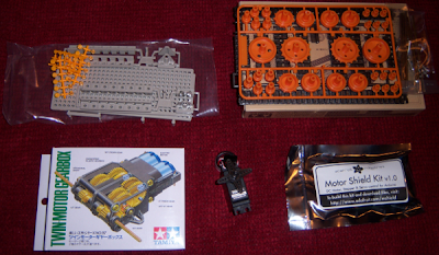
The budget for this tank is quite low, because we start with Robot 1. I chose to add a single reflectance sensor to the bottom of Wandering Tank; and remove the wall avoidance equipment. So, the budget:
Since there is no need for the parts from Robot 2, the cost is very low. I would suggest coming up with a few other things to order so that you don't pay more in shipping and handling than for the sensor. I ordered a couple sensors and of course, more of these. Time to build!
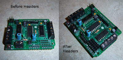
Building this robot is not as simple as ordering the parts. I could find no reliable way to attach the sensor to the bottom front of the robot. I ended cutting a strip of double sided tape up into squares and stacking them to a desired height. Wiring the robot is simple; I used digital pin 5; which is pin 19 on the Arduino. Here are some pictures as a guide:


Soldering the wires to the sensor is easy. You are simply giving it 5V to operate with, grounding it, and giving it somewhere to send data. You must add the Arduino Library For Pololu QTR Sensors to your Arduino IDE before working with the sensor.
In preparing to create the line follower; I had to do a lot of research and of course make sure I was ready to use the sensor in code. Using the sensor in code is easy. I will show the code to use the robot as a color detector. The speaker will make noise to reflect (get it?) the color seen by the sensor. As I wave the robot over a dark line; the frequency will change.
In the video; you will notice me waving the robot in the beginning with no sound. This is during the calibration phase when you want to show the sensor different colors. Once calibrated another beep announces the 'wand' is ready.
The final discussion is the approach to line following. With only one sensor; it gets tricky. If you have more than one sensor; you can find the line and keep it between two sensors; etc. With one; you have to make an effort to say on the line. As of writing this; I am aware of a few approaches:
The budget for this tank is quite low, because we start with Robot 1. I chose to add a single reflectance sensor to the bottom of Wandering Tank; and remove the wall avoidance equipment. So, the budget:
- Robot 1 ($98.00) [See this post for building Robot 1]
- Sensor - Pololu QTR Reflectance Sensor $2.49 + $4.95 S&H (est)
Since there is no need for the parts from Robot 2, the cost is very low. I would suggest coming up with a few other things to order so that you don't pay more in shipping and handling than for the sensor. I ordered a couple sensors and of course, more of these. Time to build!
Building this robot is not as simple as ordering the parts. I could find no reliable way to attach the sensor to the bottom front of the robot. I ended cutting a strip of double sided tape up into squares and stacking them to a desired height. Wiring the robot is simple; I used digital pin 5; which is pin 19 on the Arduino. Here are some pictures as a guide:


Soldering the wires to the sensor is easy. You are simply giving it 5V to operate with, grounding it, and giving it somewhere to send data. You must add the Arduino Library For Pololu QTR Sensors to your Arduino IDE before working with the sensor.
In preparing to create the line follower; I had to do a lot of research and of course make sure I was ready to use the sensor in code. Using the sensor in code is easy. I will show the code to use the robot as a color detector. The speaker will make noise to reflect (get it?) the color seen by the sensor. As I wave the robot over a dark line; the frequency will change.
/*
 * George Frick (george.frick@gmail.com)
 * October 2011.
 * Arduino Robot 3 - Sensor Wave Test
 * This isn't a robot; but uses the build line following robot to test the reflectance
 * sensor. The robot starts up and beeps to notify the user to calibrate (wave robot
 * back and forth over line), then beeps again before starting. Once started the robot
 * calls buzz with the detected color value as the frequency.
 * This tests runs continuously. The user may choose to view Serial output.
 */
#include <PololuQTRSensors.h>

const int qtrPin = 19; // pin 5 as digital is pin 19
const int buzzerPin = 14;

// create an object for your type of sensor (RC or Analog)
// in this example there is one sensor on qtrPin
PololuQTRSensorsRC qtr(( unsigned char[]) {qtrPin}, 1);

void setup() {
  Serial.begin(9600);           // set up Serial library at 9600 bps
  pinMode(buzzerPin, OUTPUT);
  buzz(buzzerPin, 1000, 100);
  calibrateQTR(); // Wave the sensor accross the color specture during this time!!!
  buzz(buzzerPin, 2000, 200);
}

void loop() {
  delay(250);
  unsigned int a[] = { 0 }; // One sensor!
  qtr.readCalibrated(a);    // It will fill the array from the sensor array.
  Serial.println(a[0]);     // Use a[0] to get the only entry.
  buzz(buzzerPin, a[0] - 50, 100); // the minus 50 is arbitrary.
}

void calibrateQTR() {
  // start calibration phase and move the sensors over both
  // reflectance extremes they will encounter in your application:
  int i;
  for (i = 0; i < 250; i++) {
    qtr.calibrate();
    delay(50);
  }
}

void buzz(int targetPin, long frequency, long length) {
  long delayValue = 1000000/frequency/2; // calculate the delay value between transitions
  // 1 second's worth of microseconds, divided by the frequency, then split in half since
  // there are two phases to each cycle
  long numCycles = frequency * length/ 1000; // calculate the number of cycles for proper timing
  // multiply frequency, which is really cycles per second, by the number of seconds to
  // get the total number of cycles to produce
  for (long i=0; i < numCycles; i++){ // for the calculated length of time...
    digitalWrite(targetPin,HIGH); // write the buzzer pin high to push out the diaphram
    delayMicroseconds(delayValue); // wait for the calculated delay value
    digitalWrite(targetPin,LOW); // write the buzzer pin low to pull back the diaphram
    delayMicroseconds(delayValue); // wait againf or the calculated delay value
  }
}
/* EOF */
In the video; you will notice me waving the robot in the beginning with no sound. This is during the calibration phase when you want to show the sensor different colors. Once calibrated another beep announces the 'wand' is ready.
The final discussion is the approach to line following. With only one sensor; it gets tricky. If you have more than one sensor; you can find the line and keep it between two sensors; etc. With one; you have to make an effort to say on the line. As of writing this; I am aware of a few approaches:
- Drive forward if on the line. When the robot leaves the line, sweep left and right until the line is found again; then continue forward. This has several problems; the largest of which is a simple 90 degree turn; in which the robot may end up going back along the line.
- Constantly sweep back and forth. I have seen this implemented on Youtube and other places. I don't like it and I don't think the robot should have to 'dance' in this way.
- I am working on this :-) Depending on how it turns out; it will be the next post. Otherwise I may settle for one of the other two approaches.

Comments